But since this webtool generates much nicer webpages than the archaic ones I used to publish, I purchased a licence to allow me to use it for personal and professional use.
This page shows my first steps with this new tool ..... uh .... toy :-)
Large fontsize huh ? I use it as it's more comfortable for me AND for collegues from the same age-group.
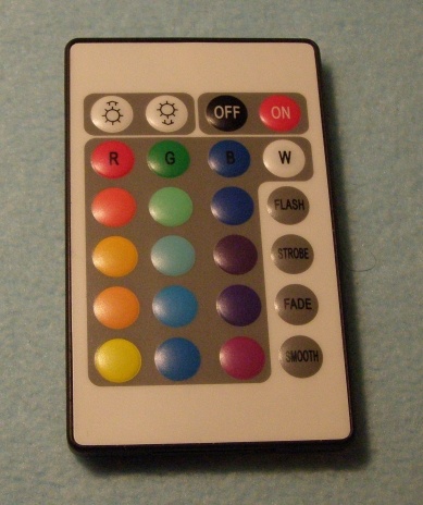
I reverse-engineered the protocol because I like this remote, but the implementation of the actual controller (the power-module) did not give the result I needed for my application.
I took a 680uH inductor, connected it to the oscilloscope, pushed a button and found:
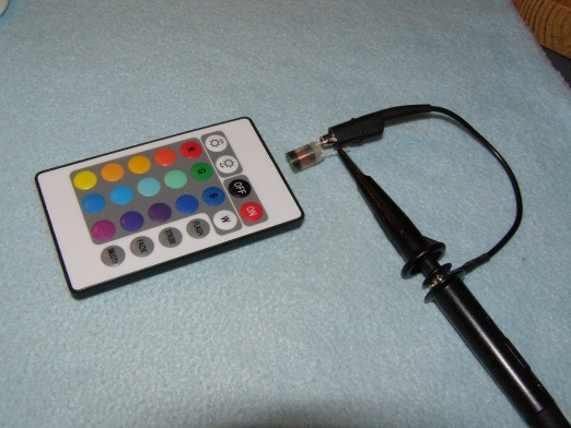
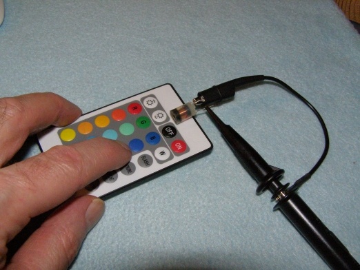
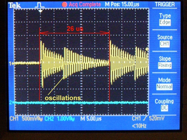
But that is not what we are looking for.
When the current is turned on, there is a sudden change in magnetic field. But also when the current goes off: so the time of two oscillations reveals the IR-carrier frequency. The measured time is a tad more than 25 us: appr. 26us. That comes down to a 39 kHz carrier. A 40 kHz IR receiver (like the TSOP1740) will work fine, although it's slightly off.
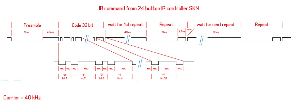
The w i d e picture is a screen-cut from what the Intronix Logic Analyzer picked up from the TSOP1740
The application software is very powerfull, and it was a piece of cake to measure the intervals. Counting 32 bit in a row is a different story.
With notes on a sketchbook I used my PCB-design program SprintLayout to draw the complete pattern, and exported it to a pdf.
A .png file for this webpage and the .pdf as a downloadable link
