
Switching Power Supply Design
Following this procedure will give you 99% chance on succes Dean .... ;)
1. How to choose a suitable inductor
First choose a frequency for the switcher. Low frequencies require
large (sized) inductors and capacitors, high frequencies cause higher switchlosses
For Nixie PS, 180V @ a staggering 80 mA ;), with an available battery-voltage of 15V:
50 kHz is a nice choice. For the Europeans: Don't go to 60, 66.6 or 77.5 kHz. I would hate that ;)
50 kHz ---> 20 us period time
What comes out, must go in: 180V * 80 mA = 14.4 W = ~ 15 W
Vdd = 15 V, so 1A @ 100% efficiency .... BPF: 80% eff ---> 1.25 A average
The inductor is used in linear dI/dt (saw-tooth with interruptions), so the peak amp will come out on 2.5 A
We need to reserve some room for the discharge of the inductor, in this case 10%
So we're looking at 2.75 A peak
This value needs to be reached in 18 us
Ul = L * ( di / dt )
Ul, dI and dt are known ---> 15 = L * ( 2.75 / 18 * 10^-6 ) ----> L = ~ 100 uH
So we're looking for a 100 uH inductor which can handle 2.75 A
Don't think you can use the average current value: the inductor will
saturate then in the second half of saw-tooth :(
Time to place an order at your favorite supplier, and while you're at
it: get some nice high-power resistors to act as a dummy-load for the
180 V, and some low R's .... 0.1 ohm, 0.22 ohm ....... (do I hear a
protest ? hold your horses and read on )
..... OR
........ have a sniff around in an old PC PS: I found f.i. these
rascals (Kudos to Bob Ross) which are on the left and on the right. The
two in the middle are new:
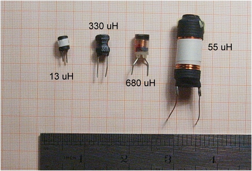
With the 55 uH there are two options: allow for 100 kHz switching
frequency, or remove the winding ( count !!!), multiply # of turns with
1.35, choose an appropriate enamel wire, suitable for 2 Amps, and turn,
turn, turn ....
OK, we have an inductor now.
Time for some testing
Write a small program for your AVR which lets Timer1 output a positive pulse
every MILLISECOND,
with a width that can be adjusted from 0 us (no pulse at all) to 30
us; by terminal-input (arrow-buttons f.i.) .... or simply a
potmeter on an ADC-channel. We call that Adjust
Tip: setup Timer 1 for Freq and Phase correct PWM (.... no, not fast PWM ...), no pre-scaler.
Top = ICR1 (or OCR1A),
OCR1B holds the required pulsewidth according to Adjust
Limit the value in OCR1B to max. 90% of the Top-value
Test this first !
Driving the FET direct from the AVR is possible, but there a few things need to be considered:
1. If the AVR goes mad (program-error or so), and it drives the pin connected to
the Gate high .... we are in trouble: the only limiting factor in the
equation for the current is the resistance of the coil: 0.2 ohm ? and
Rds-on of the FET: 0.8 ohm. Hmmm. that gives a lot of amps. So we
add a fuse in line. 2A, normal speed rating is OK.
2. The almost 5V height of the pulse from the AVR is barely enough to
drive the FET full open. It would be nice to have some higher pulse.
The answer comes form an old guy: the NE555
We're gonna use it for both considerations as mentioned above.
This circuitry was never tested the way it is now shown: this is a fresh design
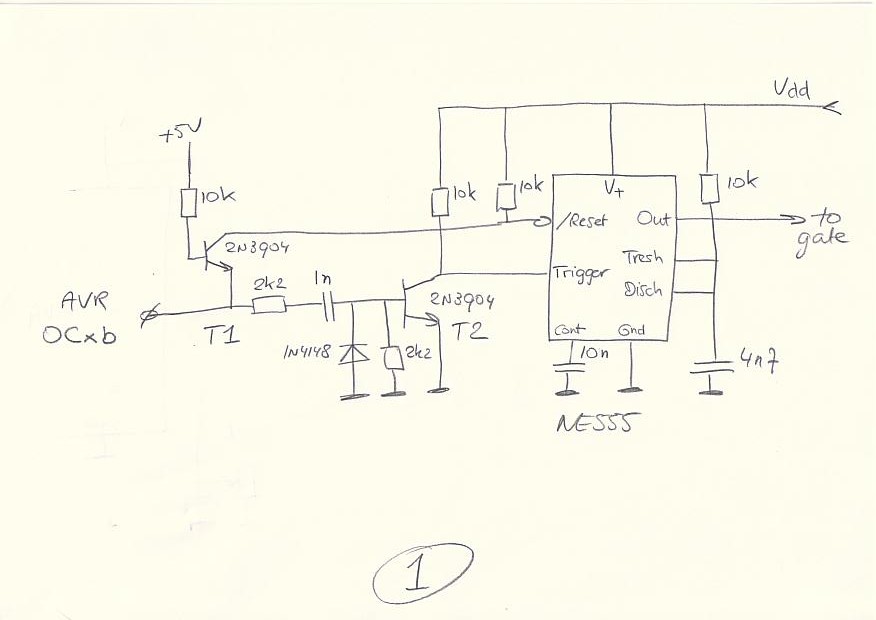
It's setup as a monostable of 40 - 60 us, non-critical value.
When OCxb of the AVR goes high, it releases /Reset via T1, and T2 generates the trigger.
< side-note: trigger has to be high when the monostable times-out ... so some circuitry was added to take care of that >
Output goes high until Reset kills that fun
..... or, if Reset is not coming within the monostable-time, it will
time-out and make the output low. Simple, safe and sound ....
Running it from 10 - 15V is fine. Directly from the LiIon's ?? Yes, 18V supply is the AbMax spec for a NE555
Let's get the show on the road
( mind you: this is just for testing ..... once ! it's a nice
experience, very educating, and FUN .... unless you touch 180 V .....
it tickles )
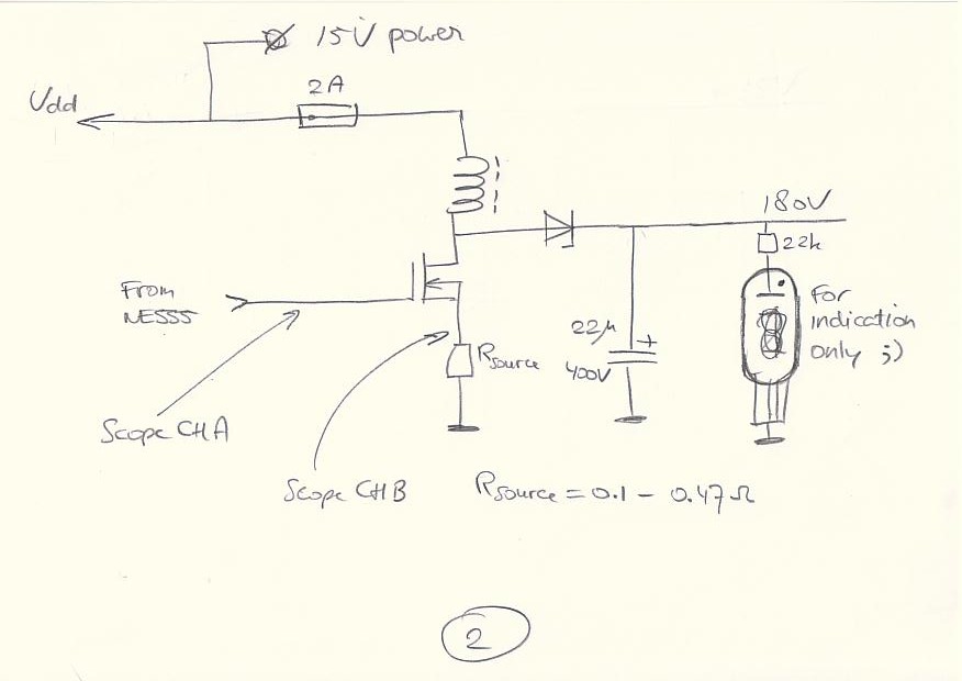
Remove the fuse
Set Adjust for 0 us pulsewdth.
Channel A of scope on Gate of Fet
Channel B on Source of Fet
Normal triggering, Ch A
Power on. Check functioning of AVR and NE555; vary pulsewidth with Adjust.
To limit the HV (180V), we use a Nixie with 22k in the anode. Don't
worry, it will not be destroyed: the repetition-rate of the driving
pulses is 1000 us, so the max output-current will be 1.5 mA max
Of course you can use the dummy-load-resistors instead of a nixie-tube !
Set Adjust to zero, and put in the fuse.
Artist Impression ;)
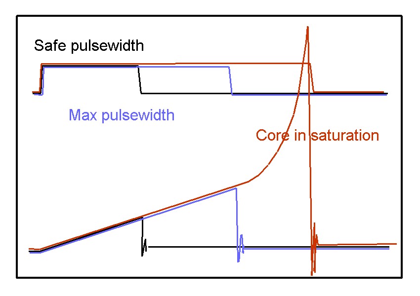
Now increase Adjust
to 5 us. Watch the sope, and see for yourself the linear increase
of the current (sawtooth). The Nixie might glow already :) : the Black curves
Now set Adjust
for 18 us (our target-value): the ramp should remain a straight line: the Blue curves
Now let's see if we can get the inductor into saturation: this is just
to show the phenomenon of what core-saturation does!!
Increase Adjust
further up, and keep watching ChB ..... at some point the straight line
will bend up. That's the saturationpoint: the Red curves
Read the max. voltage of the
line in straight-mode ;). Divide by Rsource, and the saturation-current
is known.
No need to worry for blowing Fets and/or other components: the repetition-rate is low,and keeps things safe.
After this learning-experience (was it fun?), time to move on to the final design.
The following is just a suggestion ! But it works fine (Slons is working on this principle)
Make a resistor-voltage-divider from the 180V to appr. 2.5V. Adjustable if you like.
Feed that voltage into the AnalogComparator-pin of the AVR.
The other pin of the AnalogComparator can be connected to some reference, but why not use the internal bandgap ?
Timer0 is IMO more expendable than Timer1, so Slons uses Timer0 for this purpose.
Rsource can be left out, but it's a nice thing to have there in the debug-phase.
Q. No feedback with ADC?
A. Nope. To keep the feedbackloop PDQ, the Built-in Analog Comparator is (IMO) much better for this purpose.
Q. Does it require calibration for each production-unit ?
A. No. Core-saturation (and thus trouble) comes in slow, and the margins we took are coping with that
Q. Do I need to compensate for changes battery-voltage ?
A. Hmm. Depends. If you use the max. batteryvoltage when a charger is
connected, i.e. 16.8V, and use that in the math above, you're safe ....
and even better: we did not take the voltage-drop over the Fet's Rds-on
into account yet, so using 15V as Vdd in the equation is fine.
As you'll need to monitor the battery-voltage anyhow ( to prevent
them from getting damaged ), you could consider adjusting the Top-value
in the PWM according to current battery-level
Q. That 22 uF HV capacitor .... is that a critical value ?
A. No. PC PS's are a good source btw: 47 uF or even 220 uF will
work fine as well. But watch the working voltage ( of course you
did that ..... )
Q. Is a heatsink required for the Fet ?
A. Yes. A quick calculation learns that the power-disspation is around 2 W < note: this is one of the losses >
Q. Is the Schottky-diode a limiting factor ?
A. Yes, I think it is. 1 Amp average is the rating (IIRC), and we're
looking here at an average of 1.3 A, and what's worse: the repetetive
current.
Consider this option: use two Fet's, two Schottky's, two inductors
(re-calculate for 40 mA output!). The PWM-driver can stay single (the
poor sod ....) , and the HV cap as well.
That might be easier and simpler than finding heavier spec'd components. Probably the heatsinks can be abandoned :)
Software
Yeah, I know .... it's [in-line assembly of] Bascom. Not very popular on Freaks, but
nevertheless: you can see what needs to be done, and re-write in the
language of your choice.
I did leave in the notes I made when writing this: I started of with 25 us, but that was too much for the inductor I used ...
$regfile = Attiny2313.dat
$baud = 9600
$crystal =
10000000
' 10 MHz Xtal
......
'Timer0: fast pwm, inverted compare , top=oc0a, output oc0b
'WATCH OUT: if ocr0a=200 then
'if ocr0b=0: MAX dutycycle ( 99.5% )
'if ocr0b=20: 90% dutycycle
'if ocr0b=160: 20% dutycycle
'if ocr0b=200: oc0b=LOW and stays LOW
Tccr0a = &B00110011
Tccr0b =
&B00001000
'set tccr0b.cs00 'to start the pwm
Ocr0a =
200
'20 us ; I found that 25 us drives the coil into saturation, and the
FET runs hot
Ocr0b =
200
'we start off with 0% PWM
Set Tccr0b.cs00
On Ovf0 Pc_emmer Nosave 'definition of interrupt-routine
Enable Ovf0
......
Main Slons program
......
'This interruptroutine handles the PWM-adjustment on oc0b by incrementing or decrementing pwm-pulsewidth
'according to the analog comparator
Pc_emmer:
'the routine takes 2.5 us on 20 us pwm-period: so 12.5% of cpu-resource
'save the registers that will be used
push xl
in xl,sreg
push xl
push xh
in xl,acsr
bst
xl,aco
'put AnalogComparator-bit in T
in xl,ocr0a
in xh,ocr0b
brts
incr_pwm
'increase pwm
'decrease pwm, check first max value of ocr0b
cp
xh,xl
'carry will be set when ocr0a > ocr0b
brcc Pc_emmer_done
inc xh
rjmp Pc_emmer_done
Incr_pwm:
cpi
xh,25
'minimum time of 2.5 us to let the coil push out it's energy
brcs
Pc_emmer_done
'ocr0b is too small, so no more decrements
dec xh
Pc_emmer_done:
out
ocr0b,xh
'update ocr0b
'restore registers
pop xh
pop xl
out Sreg , Xl
pop xl
Return
' Bascom
requires a Return, not a Rti
Q. : Isn't this design a bit ..... how shall I put this ..... over-killed ??
A. : Absolutely !!
Just kidding guys .....
An NE555 in a-stable mode can do the job on it's own. So without an AVR. But then we would miss all the fun
Cheers !
Some more thoughts on the output
capacitor: even the fast responding control-loop with the analog
comparator cannot keep up with variances in the 180V if a small
output-cap is used.
Let's say that we are at max. pulsewidth: in that pulse-time, the
inductor absorbs 0 - 2.75A in 18 us. That comes down to (o lucky us,
with that linear behaviour of the inductor)
1.4 * 18 * 10^-6 Coulomb
The discharge will take place in appr. 18/11 us
With an outputcap of 22 uF, the change in voltage will be: 1.4 * 18 * 10^-6 / 11 * 22 * 10^-6 =~ 0.1 V
( And with an outputcap of 1 uF: 2.2 V !! )
Let's assume that the Sodoku has been solved, and all the
Nixies are turned off, while a moment ago they were all on, so
pulsewidth is @ maximum ( I know I know, there is headroom ), then the
controlloop will ramp back as fast as possible to correct for that
raising 180V. It takes 255 pulses ( 5.1 ms) to get down do 0 pulsewidth
.... linear step down.
With 22 uF the overshoot will be 13 V .... with 1 uF ...... brrrrrr
..... do not even THINK of the consequences ..... 81 flash-tubes ....
orange .... disaster !!
So: forget about the 1 uF, and find yourself an old PC powersupply. The
470 uF 200V are the ones you're looking for. Cheap and simple. Those
will keep the overshoot limited to less than a Volt when going from
full load to zero load and vice versa
This explains why my Slons 180V PS doesn't mind if I change the load
from Zero to teh Max: it has that 22 uF cap, and the max. current is 10
times lower (of course). Slons doesn't even blink it's HV-eyes ;) when the dummyload is connected or removed.
Interesting stuff this is huh ?
Addendum:
Of course there are other ways of solving this issue. You could,
f.i. modify the interrupt-routine Pc_emmer to set the pulse-width to
maximum if the 180V is too low, and turn the pulse off if the 180V is
too high. So instead of the decrements and increments.
Even with a 1 uF the max. ripple would be just a 2.2V. But personally I wouldn't go for 1 uF.
Update
I did some ExpressSchematic today (ExpressPCB is the name of the program):
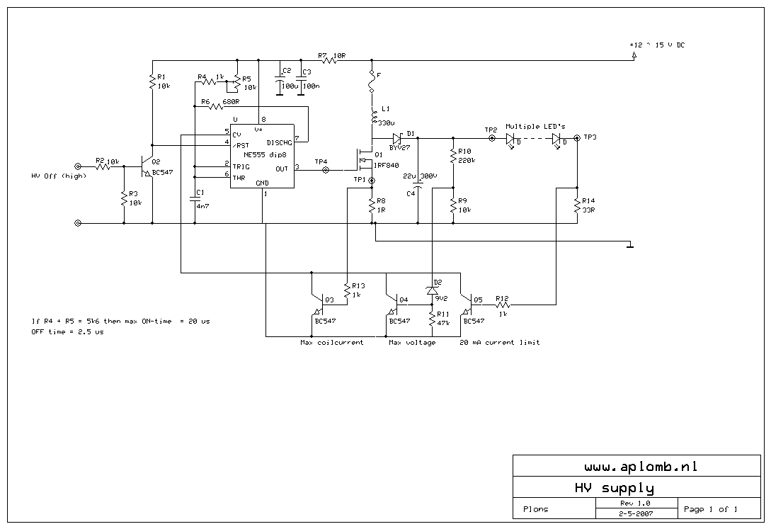
The schematic file in .sch-format can be found here
The NE555 is in a-stable mode. Q2 is there to control the HV-supply.
The ON-time is : 0.7 * (R4+R5)*C1
OFF-time is : 0.7 * R6 * C1 (fixed here @ 2.5 us)
The interesting part is in the bottom-part: might look a bit overdone
(again ;) .... but wait: this version is for engineering purposes, and
several safeties are built in.
Q3,4 and 5 control the CV-pin of the 555: when the output is active,
the voltage over C1 rises to the level of CV ( 2/3 of Vcc). By lowering
the voltage on CV we can reduce the ON-time.
Q3 turns on when the voltage over R8 reaches 650 mV, thus 650 mA. A
safety-precaution. Choosing 1 Ohm for R8 makes it easy to translate to
mA ....
Q4 is in to prevent that the voltage of this HV-supply goes sky-high
when the Led-string is not connected ot a LED is broken. When the
voltage on TP2 rises above 220V DC, the zener will start to conduct,
and Q4 is turned on
Q5 is the current-regulator: @ 20 mA through the LED's, the voltage
across R14 turns on Q5, and turns of the ON-state of the 555.
C4 is 22 uF, but 2 uF will work fine as well ..... 100 uF too :) ..... take an old PC-PS apart ....
Questions so far ? PM me.
Have fun and be carefull !!
May 3rd, 2007
I adapted the schematic for standard Nixie-use. Built and tested ---> works fine
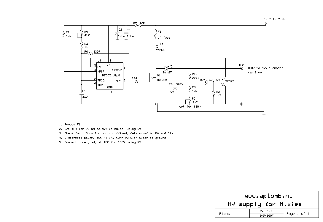
The schematic file in .sch-format can be found here
A picture of the 330uH inductor can be found when you scroll back this page.
Plons