February 2013 : another alternative for NLAS2066USG is FSA266K8X (tnx to MikalV)
Tips
and/or comments: feel free to send an email to [dragon] at [domainname
in URL that is NOW in your browser]; ditch the [ ]
February 2012 : alternative for housing Go
Alternative for NLAS2066USG: TS5A23166 farnell partnr.1053239 (tip provided by Marc K.)
or Mouser: http://www.mouser.com/Search/ProductDetail.aspx?qs=8sOby8ZxZLFhVKAuktyO6A%3D%3D
(provided by Marq87gt)
How to
fix a Dragon with mountingholes when the voltage stabilizer failed / April 15, 2011 Go
December 2009: PCB-design in Eagle5.6.0 by perlsite (Julian) added: Go
March 2009: Disclosure on why
the voltage Dragon's voltageregulator pops under certain circumstances
How to
fix the Dragon when the voltage stabilizer failed / October 29,
2008 Go
AHT-chip
identified
/ September 20, 2007 Go
New
design with 74HC244 / September 18, 2007 Go

My Dragon
From Atmel's site:
The AVR Dragon sets a new
standard for low cost development tools.
AVR Dragon supports all
programming modes for the AVR device family.
It also includes
complete emulation support for devices with 32kB or less Flash memory.
Programming Interfaces
- In-System Programming
- High Voltage Serial
Programming
- Parallel Programming
- JTAG Programming
Emulation Interfaces
- JTAG
- debugWIRE
The AVR Dragon is USB
powered and is capable of sourcing an external target.
A prototype area allows
simple programming and debugging.
The AVR Studio
online-help contains a complete list of supported devices.
I purchased one of these (thanks Sebastian, for helping me out) because
it has so many features. See the quote above.
But soon became clear that this device was vulnerable:
On AVRFreaks.net several users reported "dead"
Dragons. Or should I say "slayed Dragons" ??
Three main reasons:
1. The Dragon is USB-powered, and has a step-up converter on board to
generate 12V for the HV-programming.
However, when touching the area where this circuit located (down-left
corener on the picture), causes the voltage to go up, and that's fatal.
Dragon DEAD.
2. Powering the Dragon from a USB-port that is not "prepared" to
deliver the 850 mA rush-in current, causes the step-up coverter to die,
because of the sudden drop of the USB-supply voltage.
3. If the Dragon is connected to a faulty board (sh*t happens ...),
it's interface isn't rugged enough to withstand that abuse.
Since we know this, .... time for some action.
1. Solution is simple: don't touch the Dragon in that area. And how to
accomplish that ? Give it a proper housing.
2. Not all PC-USB-ports can deliver the rush-in current, and failing to
do so means ..... ah, we know that now.
Solution: Power the Dragon from an USB-hub with an external, beefy
power-supply.
3. Add a buffer that can withstand that abuse.
A close-up of the 2 chips that
take care of the Dragon-to-target /Reset-line:
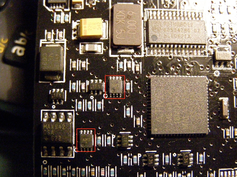
At Freaks we're trying to find out what chips these two are: the
AHT-print does reveal enough. And the Dragon-schematic is not public.
If more information is available, I'll post it here.
News:
fellow-freak
ttyridal
found out that it's a NLAS2066USG
from ON-Semiconductor
KKP, another fellow-freak, did quite some research on the Dragon's
fragility, and designed (and built) the Dragonhide:
http://n1.taur.dk/permanent/dragonhide.pdf
I adapted his design to create my own interface&protection
board.
Since my demands are less than KKP's, I used a plain 74HC08 (or HC32 if
that suits you better) for the buffering, and didn't create a Pod-board.
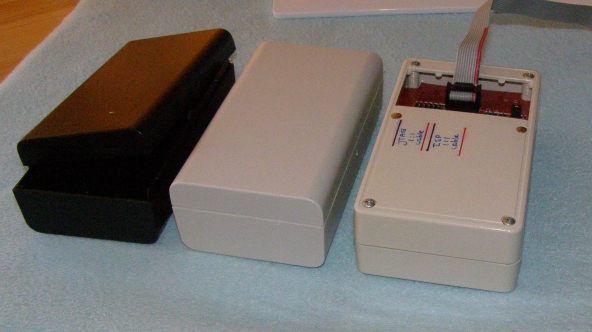
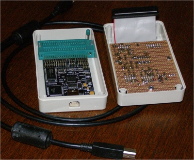
The first build:
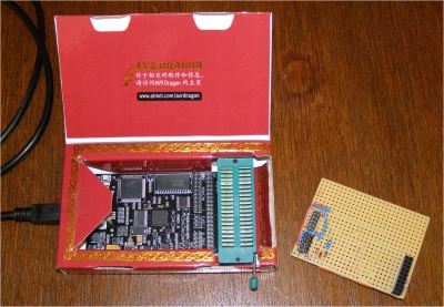
The box in which the Dragon is shipped (it's lair :-), was modified to
allow for the ZIF-socket and the USB-plug.
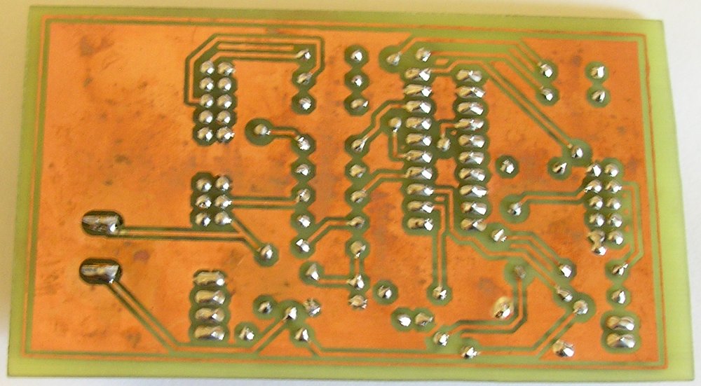
Since I used a single sided protoboard, and didn't want the connectors
to "pull" the copper-clads, the connectors were placed on the
component-side, and most of the circuitry on the copper-side.
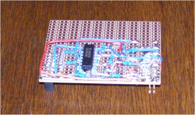
Result:
Okay ...... better than a bare Dragon, but not very good looking .....
watch ....
JTAG connector and ISP connector ......
It worked perfectly fine, but didn't look very nice
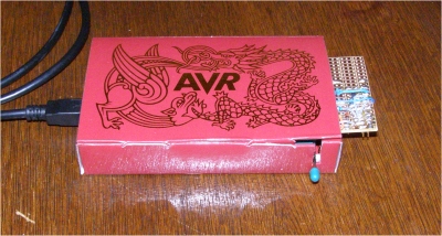
So I decided to build a proper lair for my o so fragile Dragon.
The self-tapping screws in the ZIF-socket were removed, and replaced
with M2 bolts and nuts.
Btw, sounds odd, "bolts
and nuts" for such small hardware ......
At the USB-side, two strips of dual-sided adhesive foam stick the board
to the bottom.
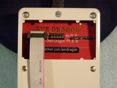
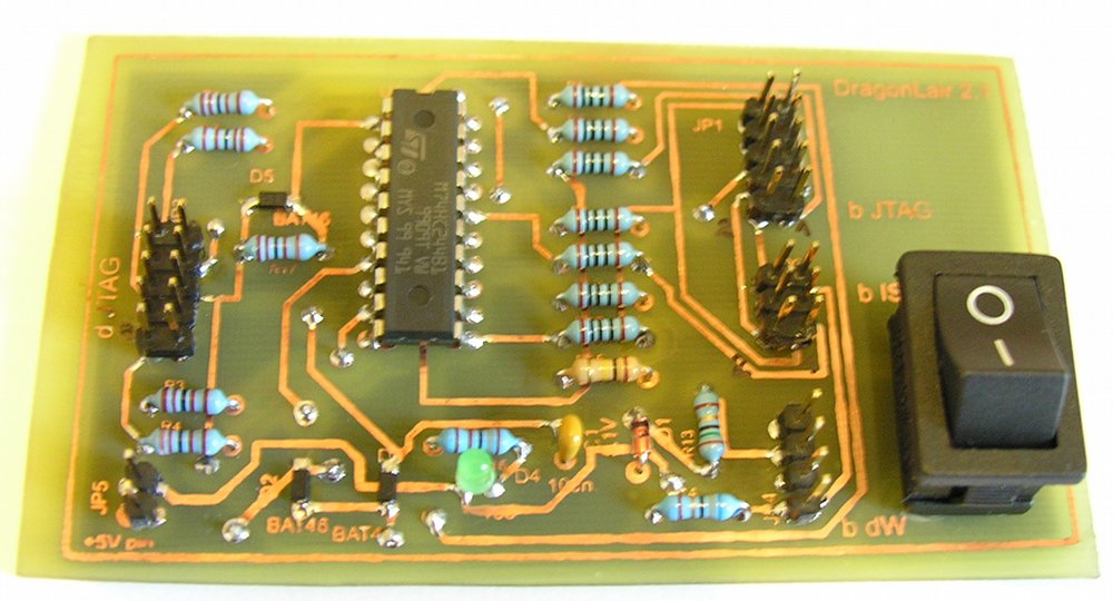
The new built interface is much nicer than the proto one, but
unfortunately I forgot to take a picture of the componentside. Two M2.5
and one M3 keep the interface in place.
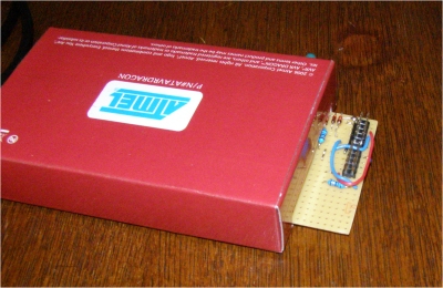
The 40-pole ribbon-cable (modified IDE cable) connects to the row of
connectors on the Dragon for JTAG, ISP and HV-programming. The JTAG
connector has all the signals that are needed for this purpose. And in
the (rare) case that I need HV-programming, all that's needed is
removing the 4 screws of the housing. I am using AVR's now for 2 years,
and upto now, I never needed HighVoltage programming. But it's nice to
have, just in case
......
From the carton of this beast, I cut an inlay. For the status-led's on
the Dragon-board, I had to find a solution: plastic fiber :-)
The visible ends of the fiber (1mm diameter) were carefully touched
against the soldering-iron. The top gets a mushroom-shape, and that's
great: they will not slide into the lair. To prevent them from falling
OUT .... some poster-gummy on the PCB holds them.
Btw, I am famous for my poster-gummy use ;-)
The left connector is JTAG, the second ISP and the third debugWire. The
fourth was intended to be used for jumper-selectable power from the
Dragon to the Target ...... but I decided not to implement it: it would
make the Dragon more vulnerable again.
The result:
Nice huh ? That's why I
stored the pictures, schematic etc. in a folder MyDragon_NICE ....
And NICE can also be read as Nard's In Circuit Emulator ;-)
( Technically spoken, the Dragon is not an ICE like in the good old
days, for the 68000 Motorola and 80xx Intel. But it comes close, and
for € 50 it's a great tool)
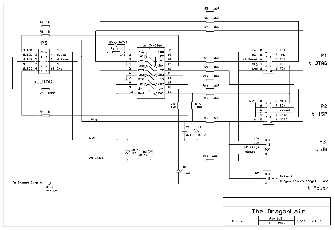
Leftclick on schematic to
enlarge / or rightclick and choose Save as
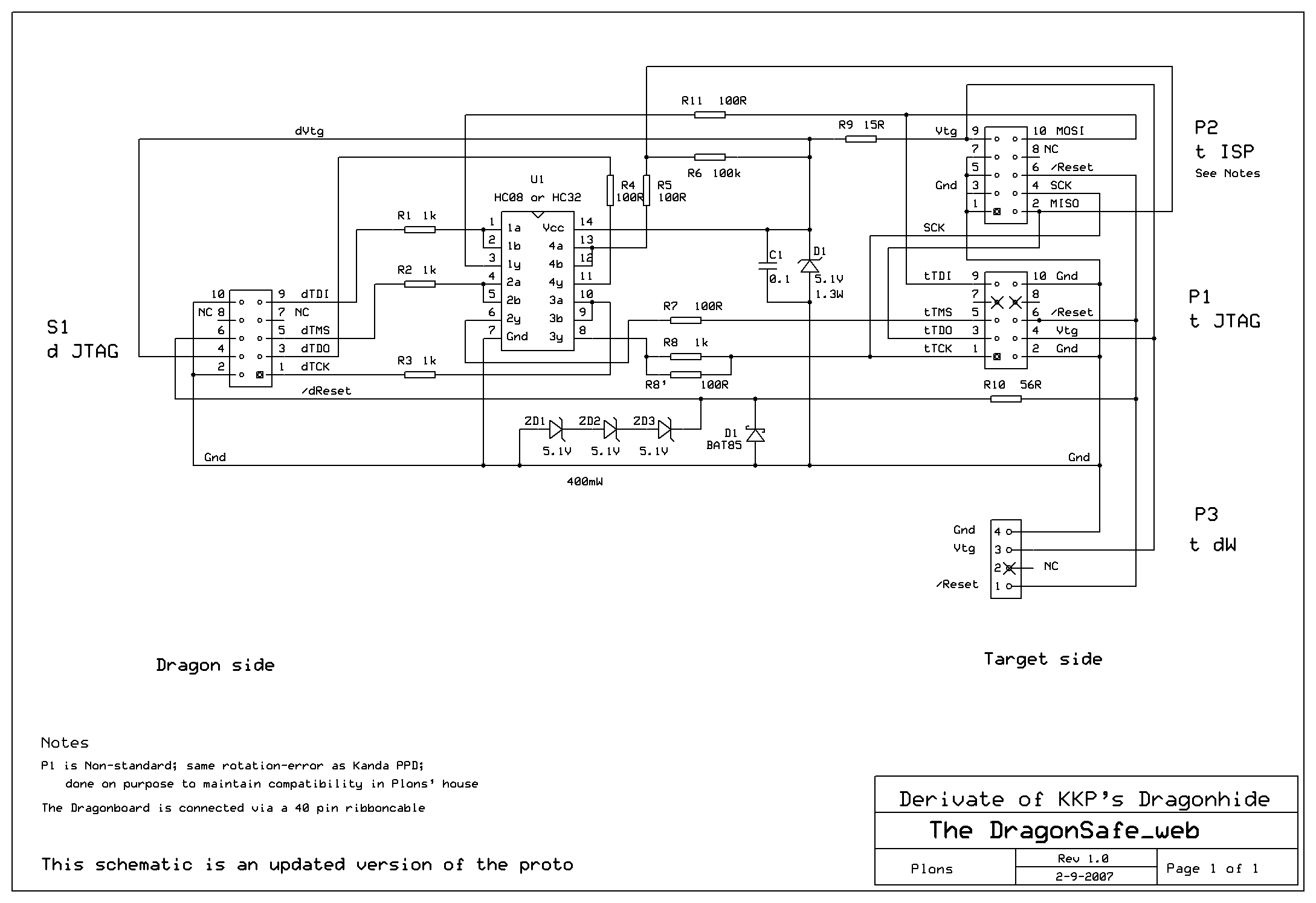
The schematic is drawn
with ExpressSch. You can download it from http://www.expresspcb.com/
The .sch-file of my
Dragonlair can be found here
TIPS:
If you plan to build
your own: Use a 74HC244 instead of the 74HC08 or 32.
The 74HC244 is a
busdriver and therefor more powerfull and can withstand heavier abuse
;-)
I should have realized that earlier.
Or: go for the original Dragonhide-design at http://n1.taur.dk/permanent/dragonhide.pdf
JTAG-ing over several meters ..... sounds like fun
...
Credits and Notes:
The background picture of this page is copied from AVRfreaks.net
The Picture from the bare Dragon (at the top of this page) comes from
the Atmel's
site
Great thanks to Kasper (KKP) for his excellent work
Thanks to ExpressPCB.com
for their nice program
All rights reserved.
Update:
Okay, I did quite some testing with the new Dragon-safe. And found that
the buffer does its job. But it does not release the ISP-lines when
done:
if the application uses these lines, there is a conflict (of interest
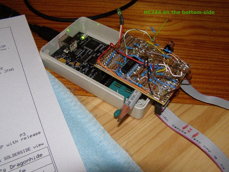
;). So I modified the proto and created a second ISP-connector
of
which the signals are buffered with a 74HC244. The /Reset-line from the
Dragon acts as /Enable for this buffer. It was a bit uncertain if it
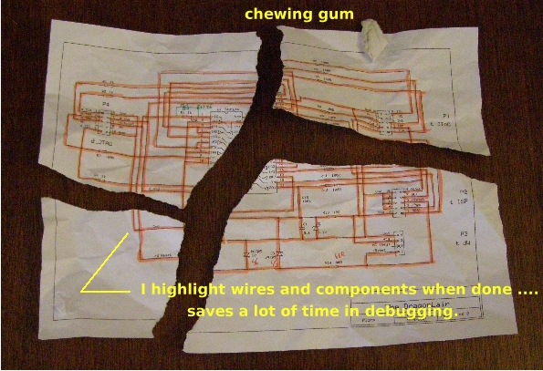
would work fine .... therefor the modified proto. Quite a mess, if I
may say so ....
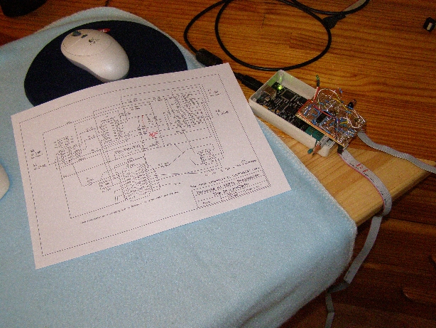
To make it easier for myself to distinguish between existing components
and interconnects, I used non-rectangular lines: and I must say that it
works !
A more detailed mess: the pencil prevents stress on the extended
10-pole JTAG-connector.
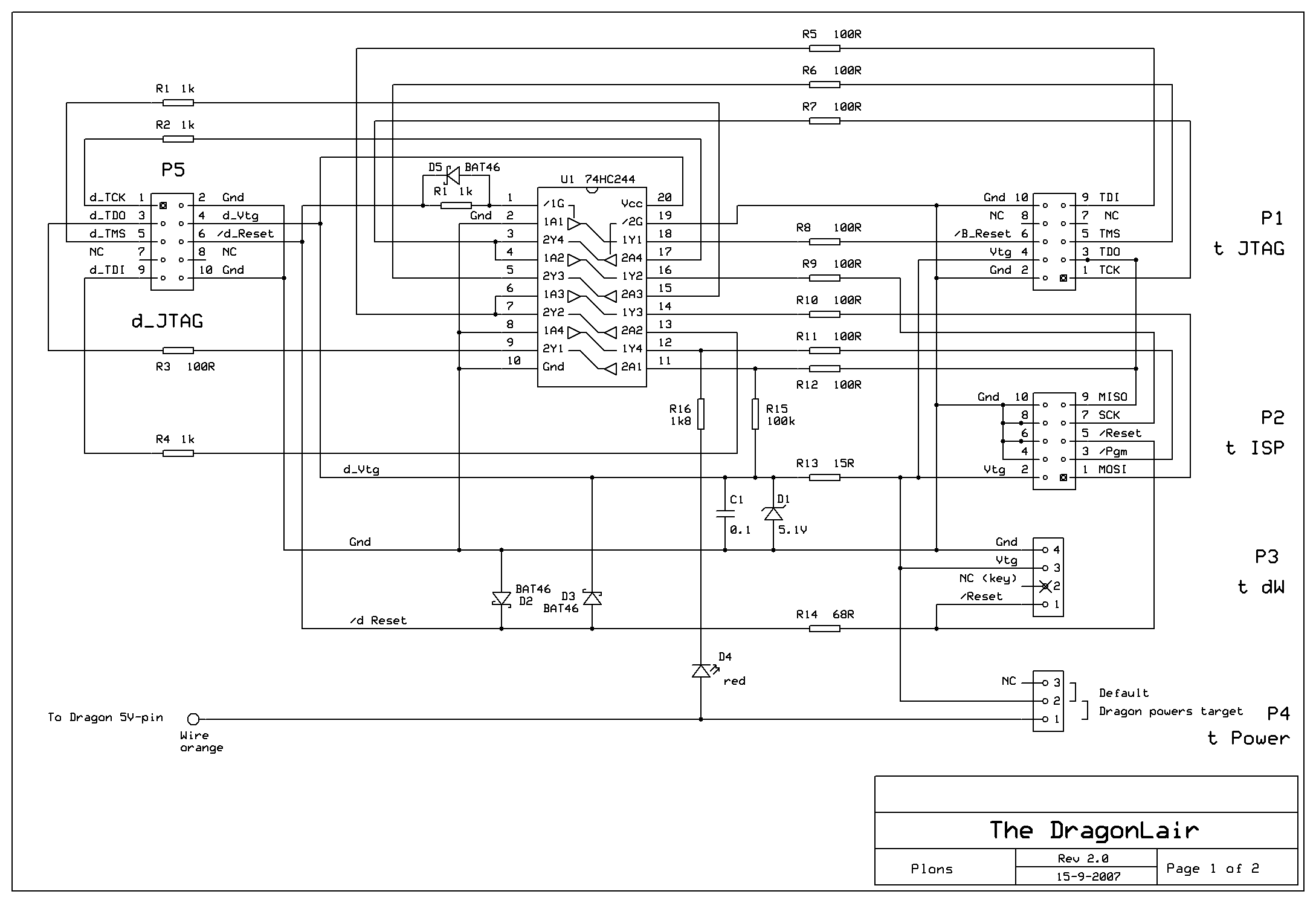
Just for a smile, here the schematic of this test-rig:
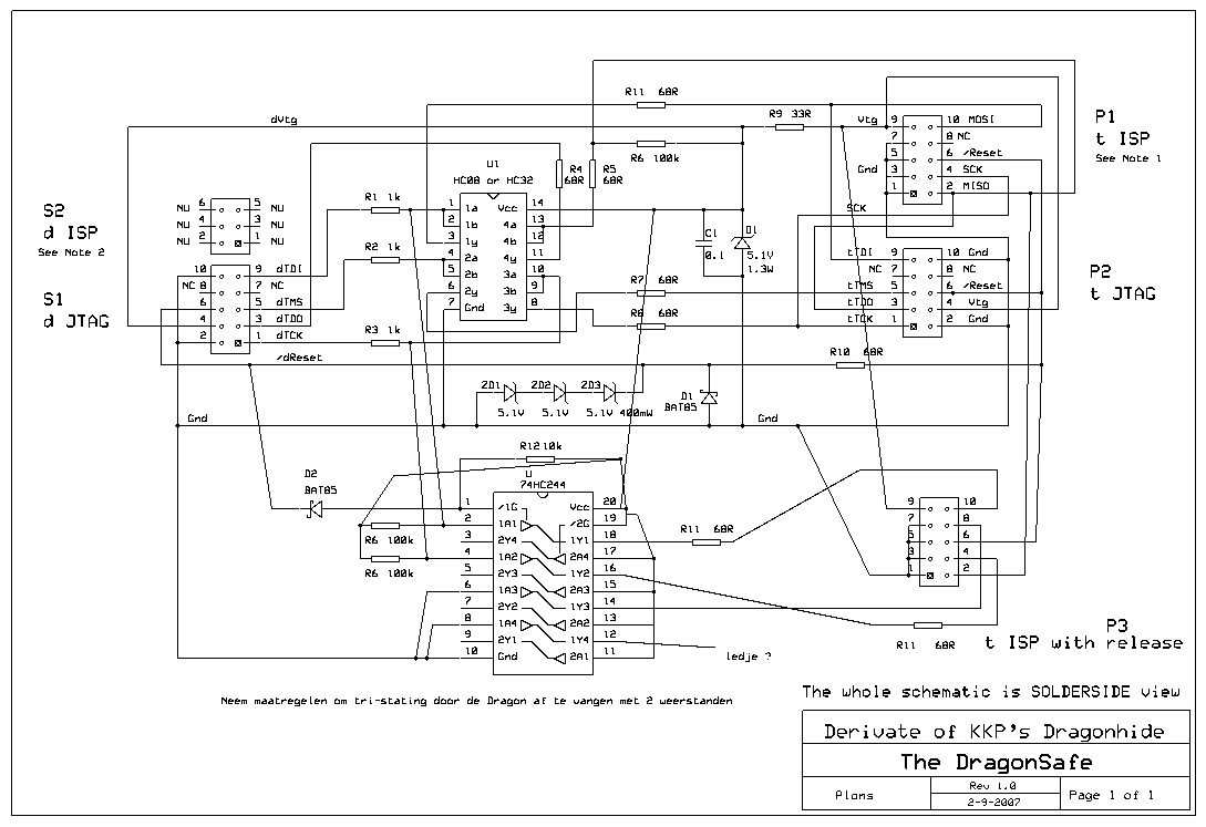
The 10k-pull-up on pin 1 of the 74HC244 in combination with the 10k
pull-up I generally use on target-boards, was too much load for
debugWire (dW) functionality. So I needed to do something on that.
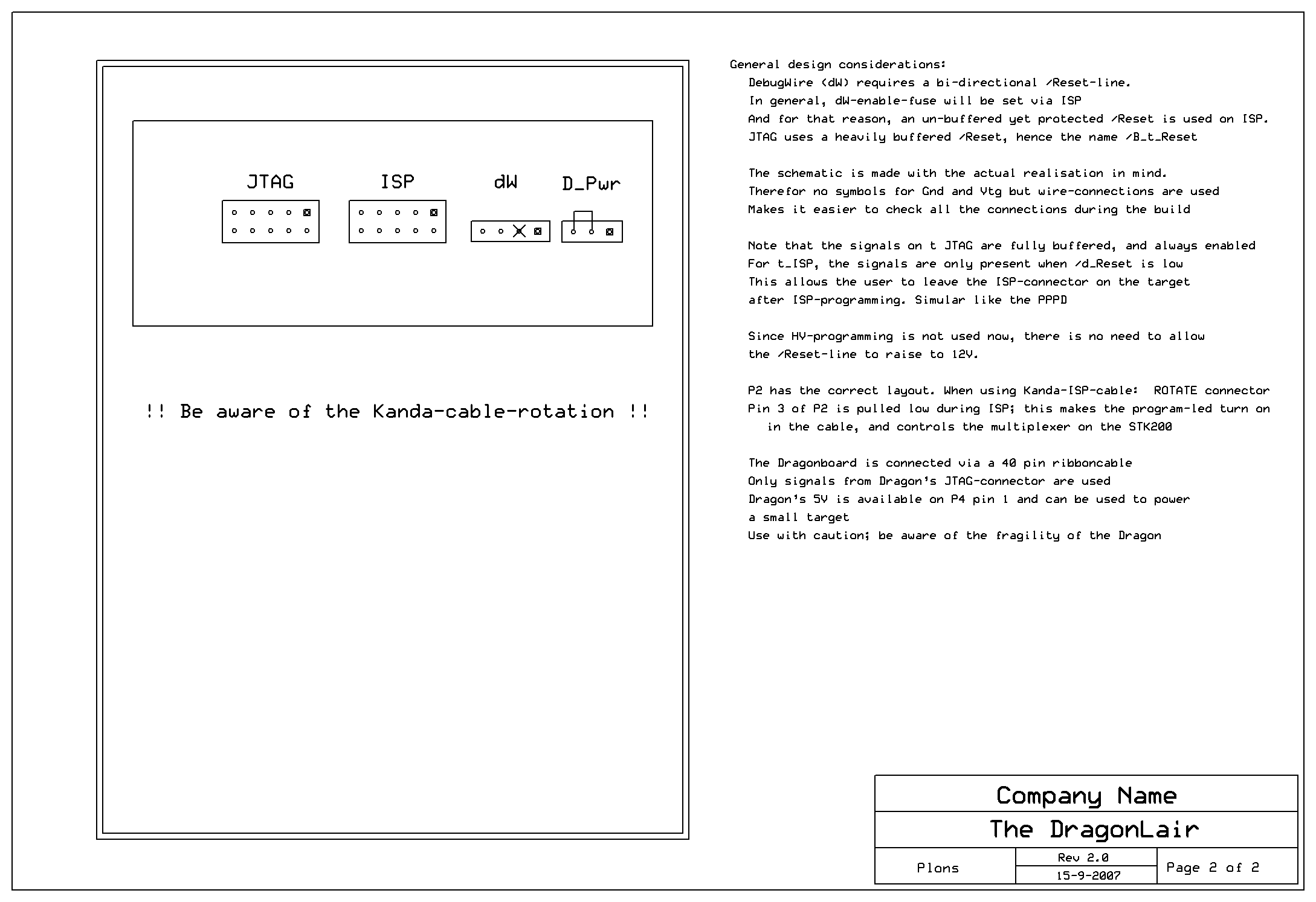
There were several other considerations .... you can find them on sheet
2 of the new schematic.
Leftclick on schematic
to view or download the 200dpi .png
Sheet 1
Sheet 2
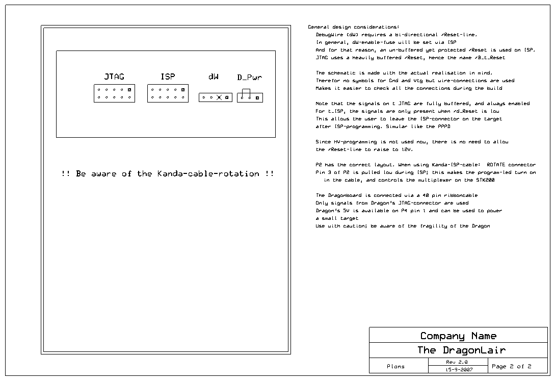
The schematics are drawn again with ExpressSch. You can download it
from http://www.expresspcb.com/
The updated .sch-file of the DragonLair rev 2.0 can be found here
As you can see, this time the 5V-Dragon-power is available
on connector P4. But use it with care.
I also added a LED to show ISP-activity. When you connect your
target-board, this LED lights up. When you power
the target, and this LED stays on, you connected the ISP-plug the wrong
way around. F.i., a Kanda cable ;-) Because of the buffering,
nothing dies (yes, I tested that)
The buffer between Dragon and the JTAG-lines on P1 is always enabled.
The reset-line comes from the buffer, and not from the Dragon itself.
This mechanism could have been applied to ISP as well, and yes, ....
that was the preferred way.
BUT: there is a good reason for NOT doing so. It has to do with dW. dW
needs a bi-directional /Reset-line. And to start dW, we need ISP to set
the dW-fuse. After that action, ISP is crippled, as the /Reset-line of
the target-board is in use for dW . To re-enable ISP, you need to do
that in a debug-session. (see Help-file AVR-Studio). To prevent that
you, as user, need to keep on swapping cables, the current-limited and
clamped /d_Reset is on the ISP-conector. Like on the dW-connector. So
you can use dW with the ISP-cable. But
if your target-software uses the ISP-lines, disconnect the ISP-cable,
and attach the dW-cable.
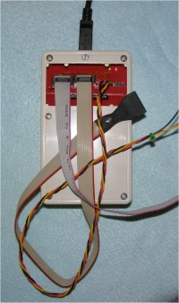
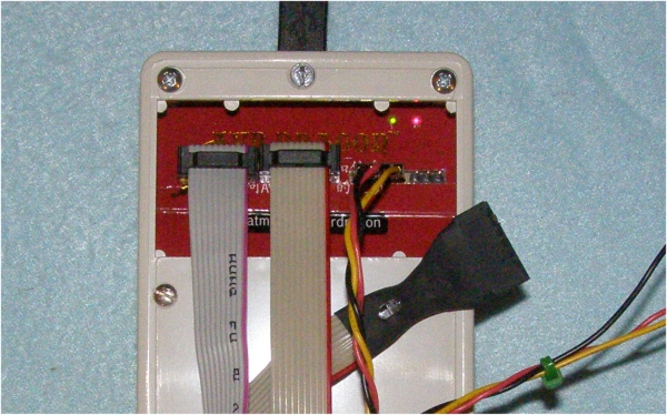
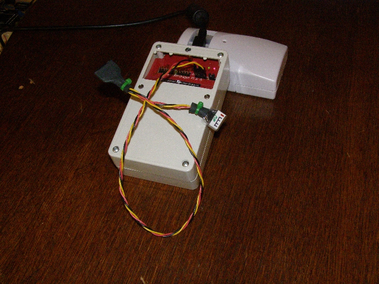
This is my dW-cable. As you can see it has 2 connectors on the end: a
10-pole Kanda-ISP, and a 7 pole Plons-ISP. And since I'm now
showing off: the 7 pole-ISP-Single-In-Line is defined with the
AVR-pinning in mind. For an ATtiny2313 f.i., it's easy to route on a
PCB. And as a second note: key-ing of these connectors is
IMSO*) a
necessity: think of Murphy. Key-ing locks Murphy out.
*) IMSO: In
My not humble but Strong Opinion
If you don't use dW, you can replace /Reset on pin5 of P2
with /B_Reset (is on P1). That makes the Lair even tougher.
(Btw, not using dW would be a pitty .... it's a wonderfull
tool)
Maybe you noticed it already .... but in case not: the zeners are no
longer on the /d_Reset. My guess is that Kasper (KKP) added
these
to allow HV-programming. Since HV-programming should be done without
any of the cables as shown here connected, I took them out, and clamped
/Reset against the 5.1V zener.
There are some more interesting notes on page 2 of the schematic.
Take f.i. nr. 2: why did I draw the schematic as I did ? Watch ....
I took it from the bin indeed ....
Repair-tip when the
voltage stabilizer has puffed its magic smoke:
My Dragon didn't have
this failure,
but is published here as a service: all rights and credits to those
fellow-feaks who sorted this out !!
The thread
where I took this info from.
With thanks to evilimp and the creator of this PDF in russian: http://www.efo.ru/doc/Atmel/pdf/ATAVRDRAGON_users_guide.pdf
From the thread, posted
by evilimp:
The
modification can be applied to PCBs A.0601.3.1000.C
Brief translation: there is a bug in voltage stabilization circuit
design.
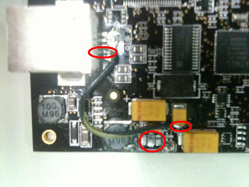
In case of
EMI chip TPS61020DRCRG4 marked with white restangle at the first
picture burns out.
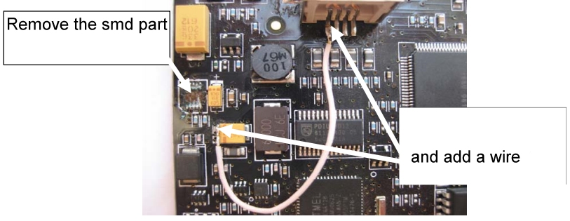
Damaged AVRDRAGON can be repaired without any functionality loss. To
repair:
a) Remove burned IC TPS61020DRCRG4 from PCB completely.
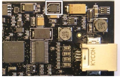
b)
Connect two PCB pads (shown at second picture) by wire.
Note from me (Plons):
Of course Atmel didn't put that component in to make the Dragon fail:
there MUST be a good reason for it.
As soon as I
found out, it will be published here.
March 2009:
Kasper Pedersen emailed me the explanation. Here it is (in my own
words):
Lots of parts on the Dragon are specified for operating on
4.5-5.5V.
The USB-spec however says:
Minimum DC voltage at host connector 4.65V
Minimum DC voltage at peripheral 4.40V
Minimum DC voltage at peripheral connected to BusPowered hub
4.150V
Using a boost regulator allowed the designer to meet the usb "must
work@4.15V" requirement.
BUT: he forgot to implement an undervoltage lockout. Which
results in an increased current consumption when the USB-voltage is
low, which results in more current to get that boosted output @5V, the
increased current lets the incoming voltage even drop further
...... do I need to iterate more ;) ?? So
in the end the boost-regulator will blow itself when the USB-power is
not powerfull enough. Funny huh ? With a powerfull USB-power the Dragon
doesn't fail, but using a not-so-powerfull one, it kills itself. Dragon suicide :S
If you are such an unlucky person, do the modification described above.
But make sure that you give the board a decent 5V supply. A powered hub
is a good source. I use one with uses a wall-wart that can supply 1.5A.
Never short on currentsupply.
December 2009
AVRfreak perlsite (Julian) created a
PCB-design using Eagle5.6.0. As a service it's available here for
download. But it hasn't been checked by me, so use at own risk !!
The Eagle-package (zipped)
Photo's of Julian's Lair :
And a copy of Julian's message:
Hi Nard,
I have attached eagle (v5.6) files, including some pdf print of
scheme and board layouts. However please take a look at my modifications
(removed optional "/Pgm" pin and respective resistor R11) which concern
substitution of Kanda ISP with regular ISP connector because I haven't time yet
to build some real board with AVR mcu to test throughly. Anyway I don't think my
changes are substantial but another look is highly welcome.
For On-Off
power switch I have used the following part JAMECO VALUEPRO R13-66A-B-02-R (from
my local store). M74HC244B1 from Farnell ( http://export.farnell.com/stmicroelectronics/m74hc244b1r/74hc-cmos-74hc244-dip20-6v/dp/1094291
).
I think I don't have anything else that is specific/different on my
board.
Regards,
Julian
Thanks, Julian, for your effort and willingness to share.
Cheers !
For later Dragons, the one WITH mounting holes: vpmedina posted his fix for a crippled Dragon on AVRfreaks.net.
Simular mechanism as with the Early Dragons. I quote vpmedina:
Hi all,
So my dragon died a couple of days ago. Never thought it would happen to me but it did.
So
I turned to google for help and I got Plons' site. But alas, it would
seem that I have a newer version of dragon than the one described there.
Nonetheless,
I tried to follow the steps as much as possible since the SMD
components look the same, albeit with different placements.
I removed the same IC and put a similar jumper from the USB connector to the yellow capacitor.
Lucky me, I got it up and running today. For anyone else with a new dead dragon, this picture might help.
Thanks !
Feb 2012:
For Gerard (LucanFahr) and Dutch fellow freaks: http://www.dickbest.nl/index.php?_a=viewCat&catId=167
Halfschaal behuizing, één hoge en één lage als DragonLair