CaveLight
The Vero-board has served several tasks .... and now this one :-)
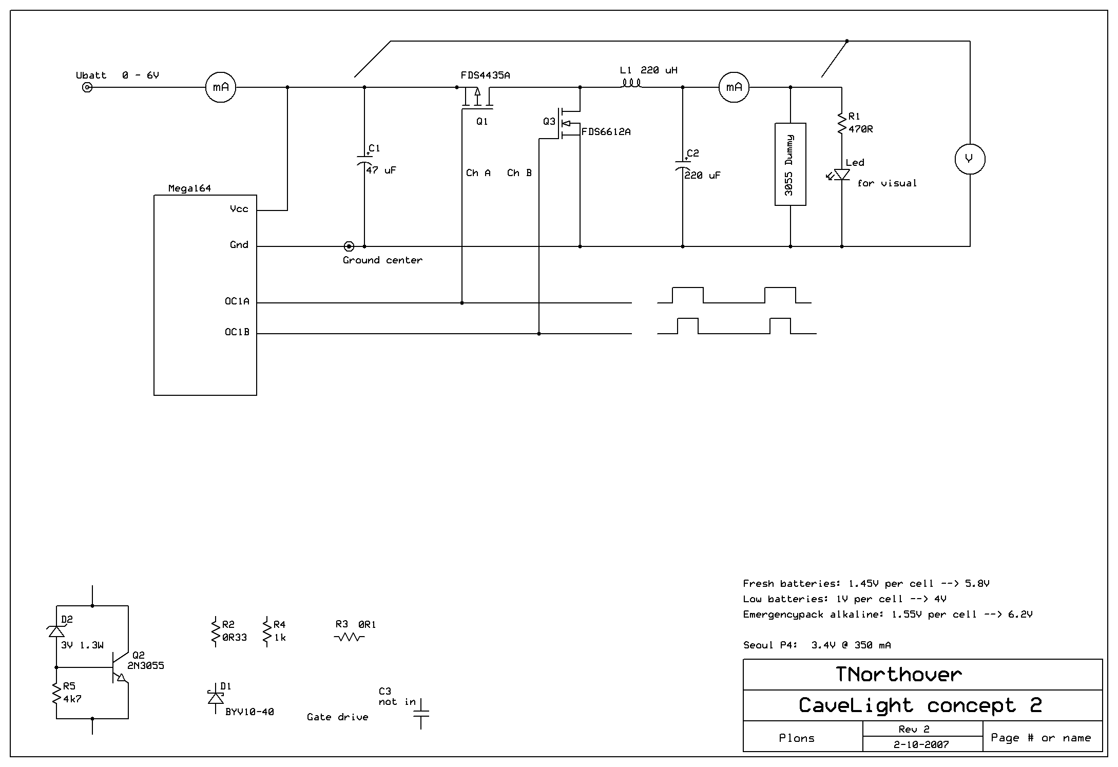
Concept 2 rev 1: two LogicLevel Fets, gates driven by one signal
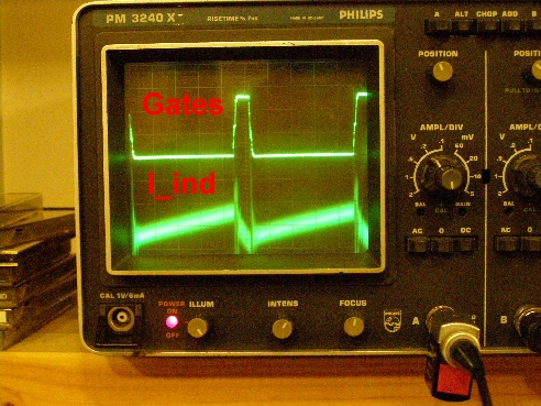
Uppertrack shows the gate(s)-drive, the lower track shows the current through the inductor
(I am particulary interested in that one .... because the choice for the inductor depends on it
As you can see, we're still in the nice linear range, no saturation ....)
That's it for tonight
Tomorrow separate drives for the gates
It is tomorow now .... click to enlarge
I scoped the groundlead (it's a very handy trick: no sense-resistor
needed .... just a solid piece of 2.5 mm² ... and a 1:1 probe
Anyway. I found there was an overlap of 50 ns between the 2 fets.
I modified the program a bit, and now it drives two fets with 100 ns between the two edges. Neat and clean.
The efficiency was about 80%, which was less than I expected: you can find the spreadsheet here
Hmmm .....
And I am eating my hat ..... as I hadn't realized that I must disable
the N-ch Fet when the inductor has dumped its energy into the output.
Did I tell what I was doing ?? 
Ossi responded with:
I can tell you what you did when not turning of
the N-Fet:
You re-invented the bidirectional up-down converter.
With the two transistors you can move energy from left
to right or vice-versa ! Depends on switching times
and inductor current direction !
If you operate in continous conduction mode
(coil current not going to zero) switching
off the N-Fet is no longer an issue.
There may be sense in the un-expected !

In the meantime I had added a sense-resistor in the source of the N-ch fet:
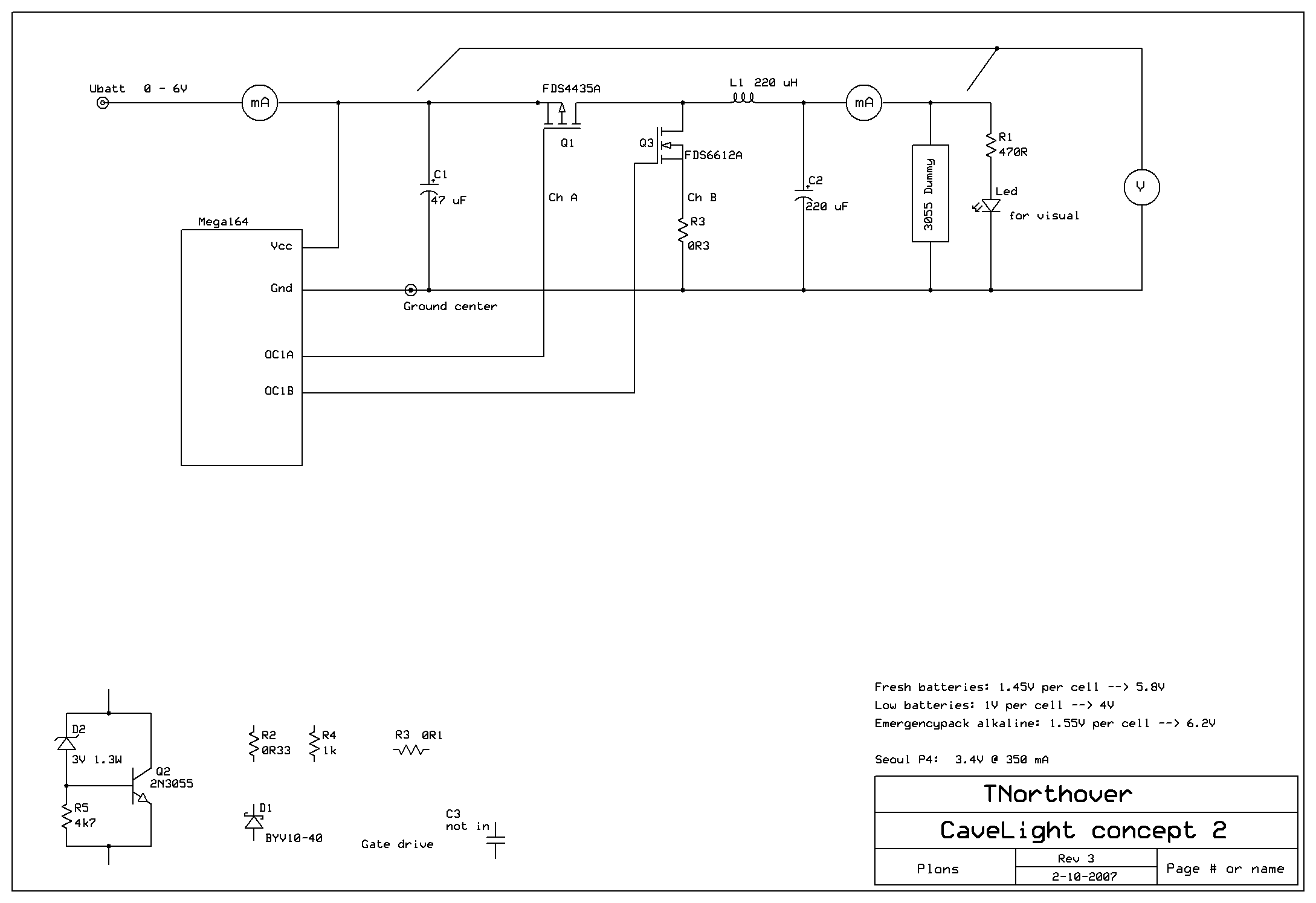
And here comes the magic:
First picture is 72% dutycycle: continuous mode
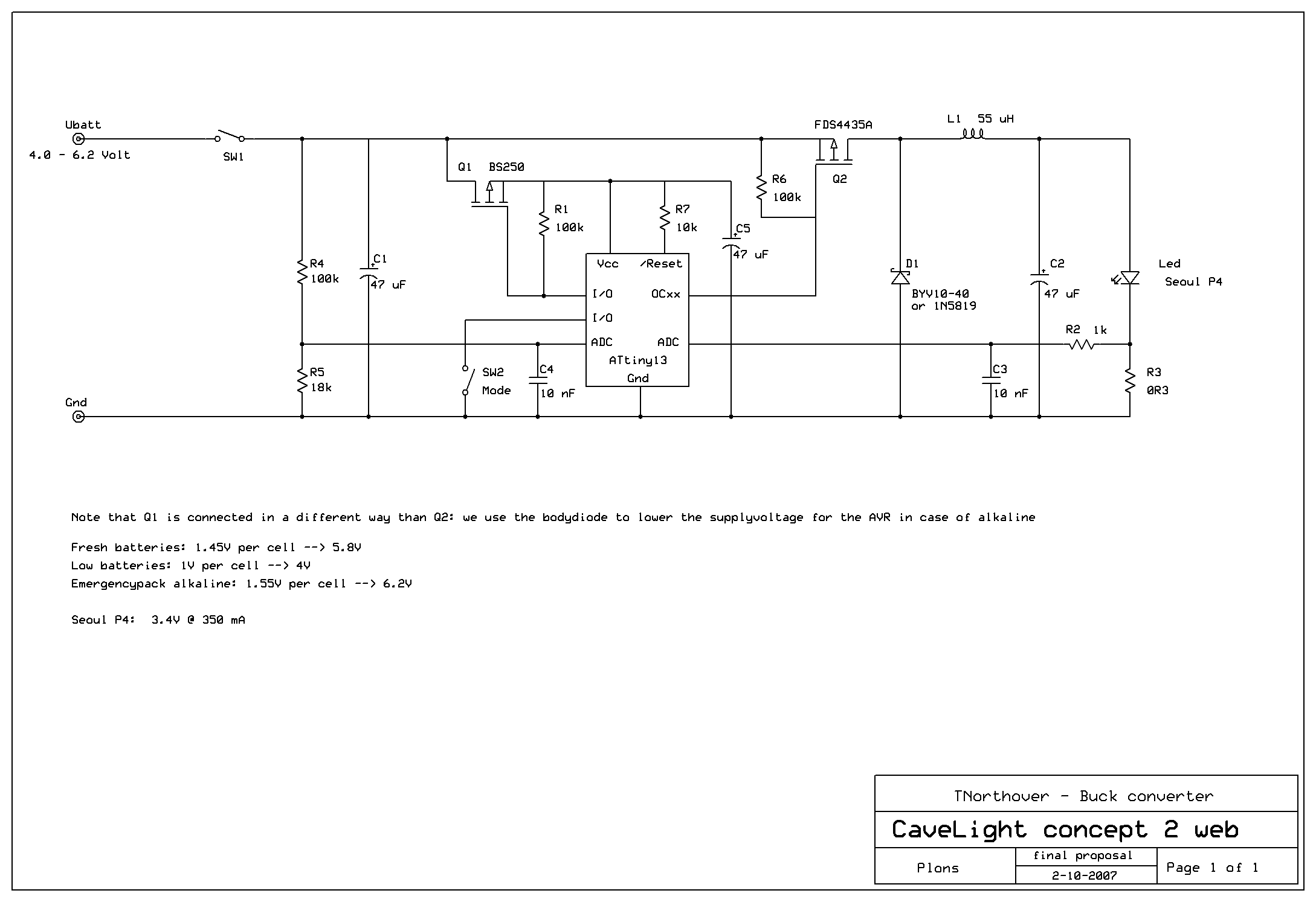
Refer to the schematic where I was putting the scope-probes.
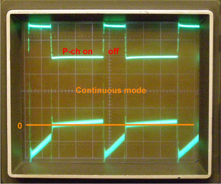
The N-ch fet is doing here what it needs to do: once the P-ch has tuned
off, it has to make a low-res path for the coil-energy. And while the
coil is still dumping the current, the N-ch switches off, and 100 us
later the P-ch comes in again. This is what we want.
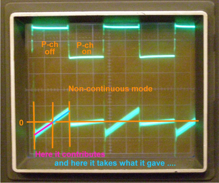
Unfortunately, at lower duty-cycles, the N-ch stays on too long: the non-continuous mode ( a better word: dis-continuous mode):
Okay, it took a bit longer than a sec to update this page, but it's there :-)
I bought a new camera half a year ago, and I am very pleased with the results.
It's an Olympus SP510UZ
Took these pictures with long shuttertimes, zoomed, with just the room-lights on.
I did a lot of measurements on efficiency. Spreadsheet in .ods-format
And found that 80% is about the maximum that can be achieved.
I wondered why. Ossi knew. He wrote:
Some estimates:
assume Uin=6V Uout=3V Iout=0.4A
==> P=1.2W Duty-cycle=50%
P channel: 50% On-Time R=0.035 Ohm Loss approx. 3mW
N Channel+0.3 Ohm: 50% On-Time Loss approx 24mW
Coil I=0.4A 100% R=0.4Ohm Loss approx 64mW
ATmega 10mA at 6V Loss approx 60mW
Subtotal (known losses ) 150mW
Efficiency: 1.2W/1.35W=89 %
You are not far away from that !
Not accounted: Switching losses, AC coil-Losses,
A 0.4 Ohm coil si quit good, perhaps your coil
has higher R.
Its really hard to get high efficiency at this low
power-level ! I think you are already quite close
to optimum !
I substituted his estimate with the actual values :
The mega164 AVR takes 25 mA @ 6V, so that's 150 mW
(the board has an
IR-reciever as well, and a few pot's ...) ....
that makes 240 mW total
.... 1.2 : 1.44 --> 83%
So it will never be much more than what I already had.
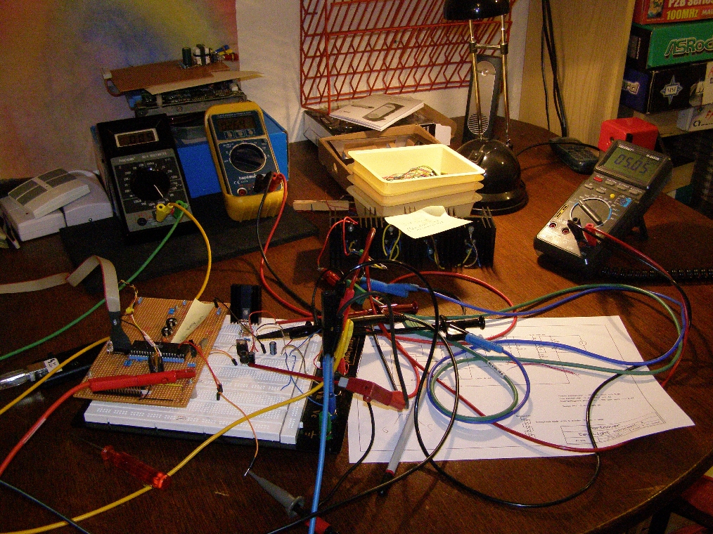
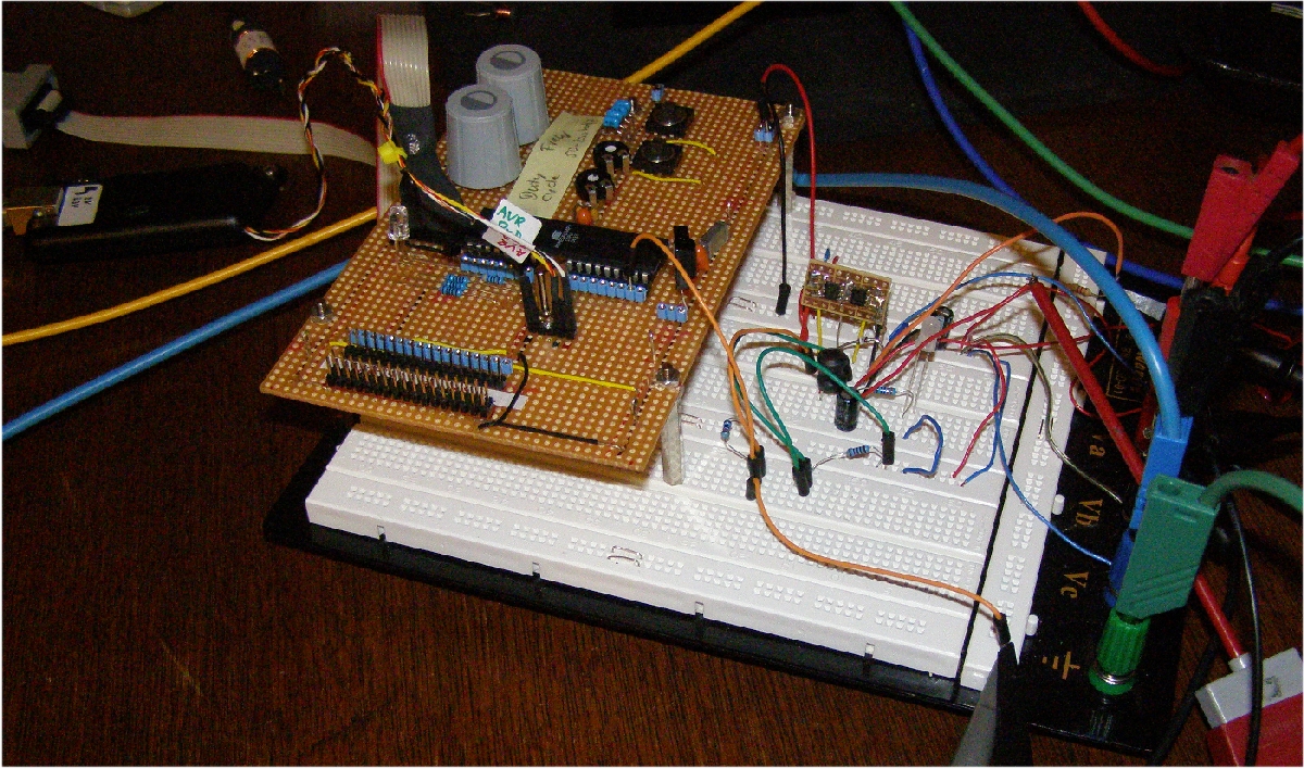
Here the test setup voor rev 4, just before the final draft (click to enlarge):
The schematic in ExpressSch-format ...
And last but not least: a picture:
There is still quite some work to do on this page .... one other day ;-)